Pre-FAB Academy
Week 2
DAY 1 - Vinyl Sticker Cutting
Machine Used :
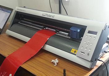
Roland Camm -1 Servo
The machine can be used to cut Vinyl, Copper and Epoxy sheets. The blade tip with in the machine cuts through the vinyl sticker and not through the white peeling section. So, eject the blade a little for the purpose.
We feeded the machine with piece. The machine can be feeded with sheet, piece or roll.
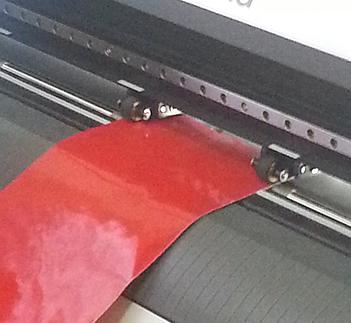
Things to note while feeding with piece :
-
Place piece near sensors
-
Place rollers apart as much as possible to get maximum cut length.
We used a piece of W= 127mm and L= 441mm (the design should fit in this area), pen force +2
Test Cut:
Before cutting the design we require, its always good to cut a small “test cut”.
By pressing the “Test Cut” button, the machine cuts a square within a circle. The test is success if the circle could be removed without removing the square.
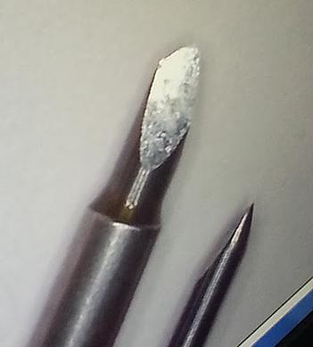
The test cut we conducted was not successful. At first we tried to put more of the blade tip outside by twisting. Still, it did not make a cut. Later we checked up with the force we were using. Inspite of the blade tip being outside by nearly 2mm, the vinyl sheet was not being cut. This indicated an issue.
So, we decided to do the test manually by applying a normal force of pencil pen and giving a cut. The force was fine, still the vinyl was not cut. This indicates that the blade is damaged.
Problem Encountered: Broken Bit
Problem Debugged by changing the Bit with a new one.
Process for cutting Vinyl Sticker:
-
Go to terminal and open fab modules
-
Input Image as .png and Output process as ronald vinyl cutter (GUI Size -400)
-
Make png_camm
-
Defaults
-
Select vinyl from vinyl, copper, epoxy (this changes the setting of velocity, force, etc accordingly
-
Choose file
-
Check dimension at the bottom and resize png if the size is not correct
-
Then load and make path
-
Set orgin and press send it.
-
Cutting begins
-
Use tweezer to remove the sticker.
-
Use white tape to easily transfer the sticker to the surface without bubbles.
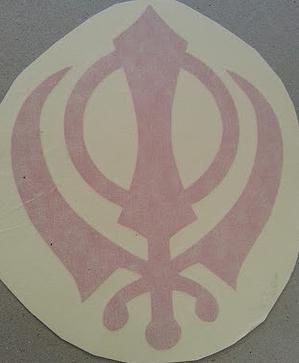
Assignment for the day:
The assignment was to load a black and white image from the internet and create a vinyl sticker.
DAY 2 - Laser Cutting
In Laser Cutting the main principle is to concentrate the laser beam to the point where cutting is to be done. So, things that can't be burn with laser cannot be cut with laser. Only organic materials can be cut with laser (like paper, cardboard, acrylic, wood). Synthetic materials like plastic cannot be cut with laser.
The laser beam used for cutting is laser class 4, which is so powerful that it can damage eye. Safety comes first, hence extra precautions must be taken to protect vision and laser cutting machine must not be used with the lid open.
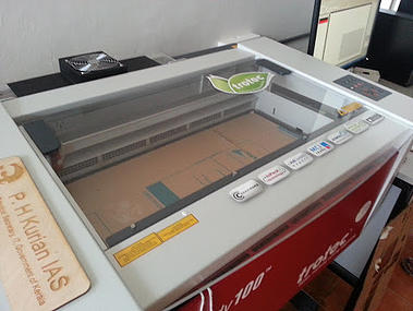
The machine used for laser cutting in the Fab Lab is Trotec Speedy 100 Laser Engraver
Machine Details :
Trotec Speedy 100 Laser Engraver
Laser type: CO2 laser
Work area: 24 x 12 inch
Max. workpiece height: 6,7 inch
Laser power: 12-60 watt
Atmos Laser Exhaust System
Filter system sends the exhaust out, removes fumes and releases clean air. Filter over time has chances to get clogged. Filter system is optional and is required only in interior areas.
Reading on the Exhaust System LED screen are :
Filter volume : 180 m^3 / hr
Filter : 0%
Activated Carbon : 6%
Step 1 : Loading the material in the Machine.
Initially the material is loaded into the material. For testing and prototyping purposes we use cardboard. Acrylic is expensive material for this purpose.
Points to note while placing the material
-
The material should lay flat. Use painters tape to affix the materials along the corner.
-
Place only natural materials.
-
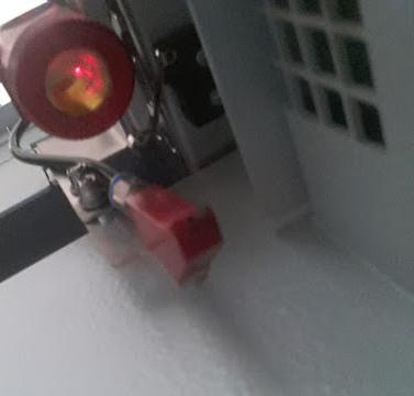
Focus the Laser pointer beam.
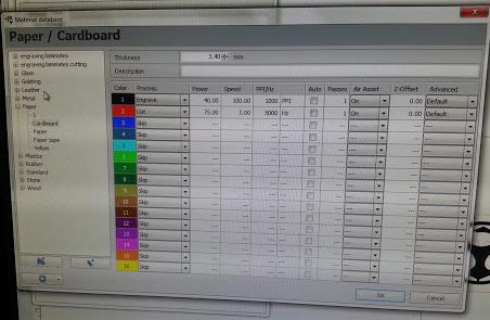
Step 2 : Setting the power and speed for ideal cutting of the cardboard,.
The cardboard thickness is 3.4mm, to cut through thicker material you need to increase power or reduce speed. But it is not recommended to reduce speed as there are chances to catch fire. The material gets blackened, it indicates the beginning of fire. So, remove cardboard and switch off the machine.
The power was changed from 50% to 75%, to find the ideal power required to cut the cardboard placed.
At 75% of power, the cardboard cut was optimal and not over burnt. So, 75% to 80% is the right limit to get the cardboard unburnt and easily removed.
Assignment for the Day
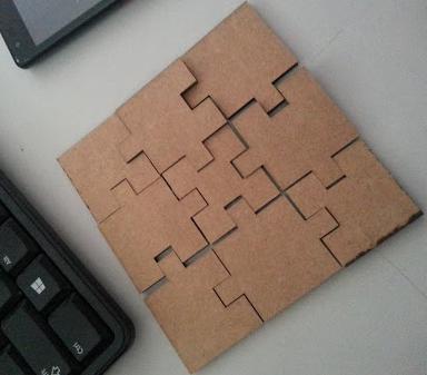
We were asked to laser cut any product or design we have made. I have decided to make a jigsaw puzzle ( 9 by 9 ). As franc suggested, I initially sketched the design on the paper and later on used CAD to draw the puzzle. The lines to be cut by the laser cutter should be red and for engraving using laser cutter black colour should be used.
Problems encounted :
While designing the puzzle in the CAD, I traced the puzzle lines to be cut more than once. These lined was traced by the laser beams too. This resulted in a few areas of my jigsaw puzzle to become blackened.
Final Product :
DAY 3 -3D printing
3D printing is an additive manufacturing process. layer by layer plastics get added to make the final product.
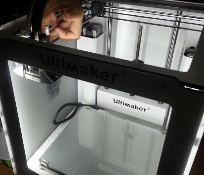
3D printer used is Ultimaker 2
Machine Details :
Build Volume : 223 mm by 223 mm by 205 mm
Resolution : Upto 20 micron
Speed : 30mm to 300mm
Nozzle Temperature : 180 – 260 degree celsius.
The objects for 3D printing is made using Antimony.
In Antimony, objects are made using it's mathematical formula. So Antimony is only for solids and not for objects that are not closed.
Using Antimony
A .stl file is then made to a gcode file and loaded to 3D printer for printing. Several issues can happen while 3D printing.
Assignment for the Day
Each person create a Fab lab usable product using 3D printing.
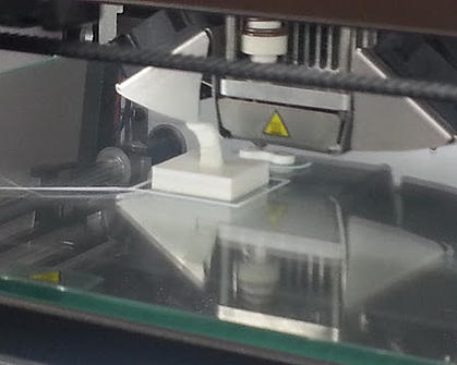
I made a hook to hang the name plate. The hook is made by combining an extruded cube of dimension 2cm*2cm and curved holder.
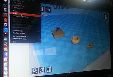
After the hook was created in .stl file using antimony, it is then converted to gcode using Cura software and loaded in the sd card and sent to print in the printer.
Problems that can occur during 3D printing :
Franc explained the problems that can be encountered during 3D printing and how to trouble shoot them from the following site : http://support.3dverkstan.se/article/23-a-visual-ultimaker-troubleshooting-guide
The problems include :
-
Pillowing
-
Elephant's Foot
-
Shifted layers
-
Under Extrusion
-
Filament grinding
-
First layer not sticking.
Some of us did encounter Under Extrusion issues.
Assignment Output :
My hook was printed as per the designs. But, Frank suggested a better design for the hook. This was to increase the strength of the hook so that it doesn't break off easily. So, I need to build it in antimony and put it to print.
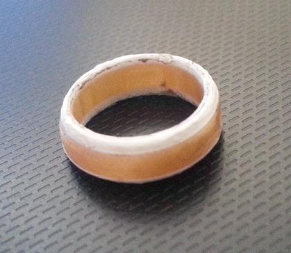
I also designed a ring which I made multi colour by removing the filament manually. It is also possible to do multi colour from cura software itself.
DAY 4 -Catch Up Plan
Day 4 started off with franc narrating the importance to begin off with the catch up plan for the documenting process.
We were all lagging behind the documentation process and franc instructed us to follow the catch up plan. By Catch Up Plan what he meant was to document today's work and at the same time document one of the previous days work. That is to move forward and pick one from behind. This keeps you on track so that at the end of week 3 your documentation would become completed.
Documentation is a very important process in the academy and it is essential to document all your works. Also, documenting the problems encountered and the troubleshootings done would be helpful for future references. Hence, he suggested to make a trouble shoot table for the problems encountered.
My Catch Up Plan :
I was lagging with the documentation of the first week and the first three days of the second week. This was mainly since I missed the first week session and was trying to catch up with that in the second week. Tasks for the first week is completed except for installing antimony, for which still I face a trouble.
I am already on track with my catch up plan.
On day 4, I did start off with documenting with the assignments done on day 3.
I am planning to finish off with the documenting of the entire thing by this saturday and sunday.
2. Design Mold using Antimony
Today's assignment was to design a mold and mill a mold. For this we need to design the mold to be milled initially. Franc suggested to use Antimony to create the mold designs. It is also possible to use the other softwares such as solidworks, sketch up. Roland modela is the used machine. Roland modela is a mini desktop milling machine.
A mold is basically a hollowed-out block that is filled with a liquid or pliable material. The liquid hardens or sets inside the mold, adopting its shape. Molding is done for creating multiple objects of the same shape. Wax blocks are used to create the mold.
Things to take care while designing a mold :
-
Always leave 5mm minimum of border
-
Depth that the bit can go should not be more than 5mm, if gone further then breaking can occur.
-
The height of the object should not be more than the size of the mold box.
Always remember that “No machine is perfect to perform all activities”. Hence, problems can encounter even while using a Roland Modela MDX-20 for milling a mold. The problems that could encounter during the mold creation are:
-
how much depth the bit can go
-
crashing
When crashing occurs the bit becomes misaligned and the milling doesn't occur as expected. This results in variation of shape. To avoid crash a setting called clearance must be set. With clearance the tool would be placed as such that the crashing doesn't occur.
There are two bit sizes. (1/8) bit is to remove huge pieces and the another bit (1/16) to do finer works.
Setting the origin and saving the coordinates are really important.
The mold should be made tight so as to have a minimum clearance
With molding, always keep in mind to " Do what the tool/bit can do and not what you want to do "
So your design should always be tool-friendly design...!!!
Molding and casting
For molding and casting there are various smooth on used.
Here we use “Smooth on Oomoo 25”
Oomoo 25 is a fast cure pourable silicone for making pour on rubber molds. Parts A and B are mixed in equal amounts (1:1 ratio). Mix the liquid thoroughly but not aggressively. Pour over the prepared milled model and let it cure to a solid flexible rubber mold. Take care that bubbles are not formed in the rubber mold. Pot life is 15 minutes and rubber cures at 23 celsius. So it is important that the storage is done at a temperature less than 23 celsius.
These are Expensive products with limited shelf life. So use as soon as possible.
Typically costs of Smooth on Oomoo 25 is around 3250 INR or more and it has a shelf life of around 6 months.
Read manual before doing the process
Mixing Technique
Mixing can be done by volume or by weight
To avoid bubbles the mixing should not be done aggressively and follow a specific to and fro movement instead of stirring. Bubbles can result in imperfect mold and the molded objects too aquire air bubbles due to these.
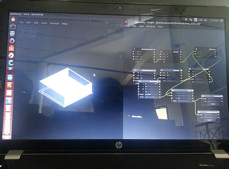
Using Antimony to create Mold Design
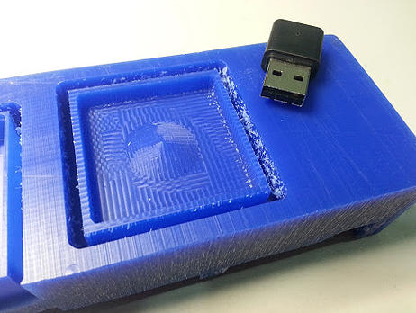
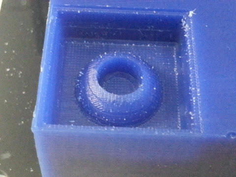
I created a mold with a cone in the middle. The dimensions of the mold was 50 mm by 50 mm by 15 mm
On Day 4, we could not complete off with mold making and molding process. This was due to the reason that the modella had only one metal board. Franc suggested to laser cut acrylic sheets and make multiple boards. Metal boards are used only to mill circuits and not wax. So, puneeth took the dimensions of the metal board and designed acrylic sheets in CAD software. The acrylic sheets were laser cut and made by the evening.
DAY 5 -Milling the Mold
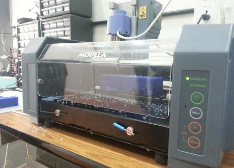
The mold was milled using a precision desktop milling machine the Roland Modela MDX-20.
Machine Details :
Roland Modela MDX-20
XY table size : 220 (X) x 160 (Y) mm
Acceptable material : Wood, Plaster, Resin (modeling wax, styrenform), Chemical wood
Acceptable tool : End mill, Drill
Bits Size : 1/64, 1/32, 1/16, 1/8, and 0.01 mm from carbide
It's an all-in-one scanning and milling device.
After the design is sketched in Antimony or any other 3D sketching softwares, the sketch must be loaded to the machine. It is important that the machine must be set up initially.
Setting up the Roland Modela :
-
Clean the machine, remove all the dust particles and debris.
-
Take the board and fix the wax mold onto the board with a double sided tape .
-
Set the correct milling bit in. Initially for rough cut we use biy of 1/8th.
-
Use an allen key to fasten the bit. Be extra careful not to over tighten the bit
Note: Always place back the bits and the tools are on a magnet on the machine.
-
Move the machine to the zero point pressing VIEW button.
-
Use the DOWN button to set the machine bit near to the wax. Keep pressing DOWN button until a small shave of wax gets removed. You could lower the bit using allen key also, but franc finds the other method preferable.
-
Loading the Mold Design to Modela :
-
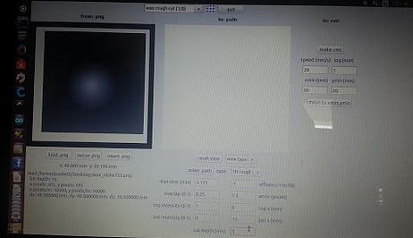
Next open the Fabmodules
-
Select input format with the designed mold's .png format and output format as roland MDX-20 mill (.rml)
-
make_png_rml
-
Load the png image
-
make path
-
Adjust all the settings, move the X and Y axis to the required plot
-
Make rml and send for print
Problems Encountered :
-
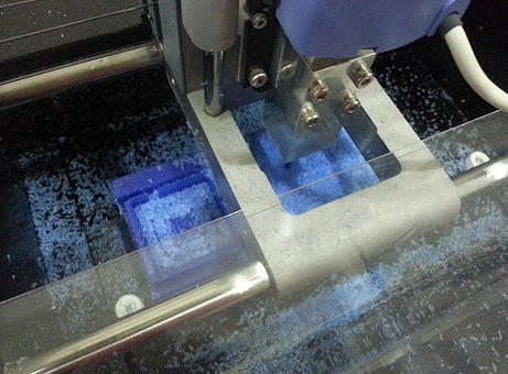
When the Milling Began, the sound from the machine varied after a few seconds and there was a fluctuation in the lights. The Milling process stopped abrutly.
-
We rechecked the operation and began the milling process again. But, still the same problem was encounted.
-
So, we initially guessed out that this might be due to some power fluctuation issues and decided to change the power adapter.
-
We re-started the milling process and still the same issue was occuring.
-
Eventually the reason for this abnormality was found out to be “Loose Bit”
The Bit was tightened and the problem was debugged.
The rough cut was done with the 1/8th size bit and then the bit was removed to 1/16th size bit to do the fine cut.
DOCUMENTATION
My journey through the Pre- Fab Academy workshop...